Gas System Crossover Replacement
It is November, the weather has turned cold, and thermostats are ratcheting up to keep homes and businesses warm. Ounces of pressure in a 0.375-inch residential gas pipe becomes hundreds of pounds per square inch, upstream, in 30- and 42-inch pipes as millions of thermostats call for heat. The infrastructure required to service the energy needs of major cities is large, well built and designed to last for decades. The downside is valves, flange joints and pipe itself will not last forever. Despite the use of the highest quality steel, valve seats and gaskets, time and the high-pressure flow of gas will gradually wear on these components. When this happens, a valve may not completely shut off and gas will continue to flow. Gas companies do an outstanding job of maintaining the integrity of their gas systems and this crossover replacement is a good example that.
In addition to leaking valves the pipe is subject to corrosion from electrical currents either induced through a/c electrical transmission and distribution voltage, or from dc current. This can be offset by using cathodic protection to prevent the pipe itself from shedding electrons and reducing wall thickness. A 50- or 60-year lifespan is typical, and a testament to the quality of engineering, design, materials, and construction used to build natural gas infrastructure.
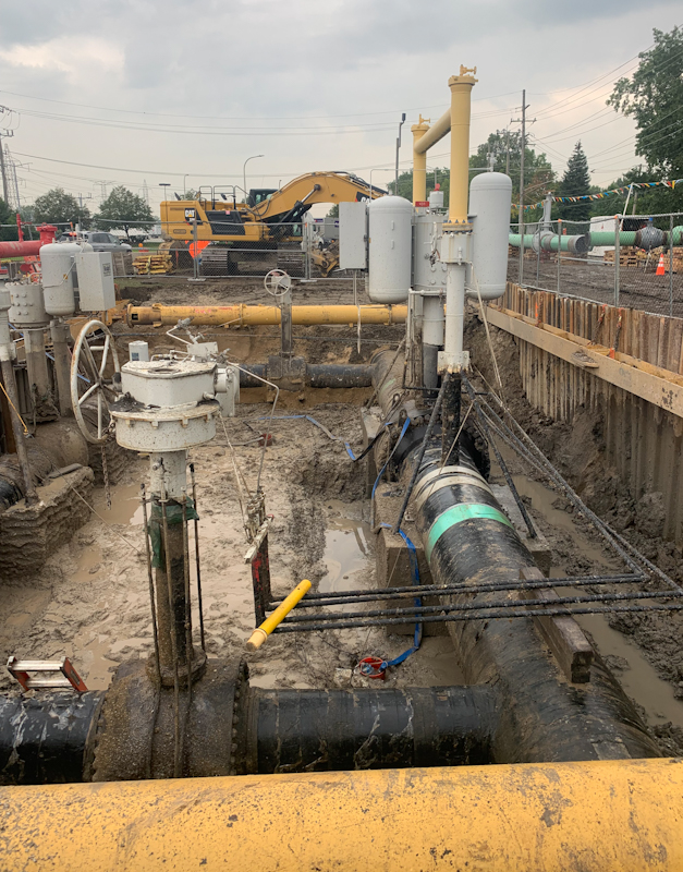
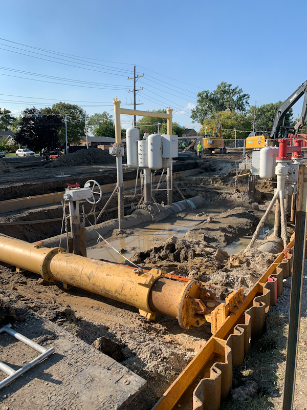
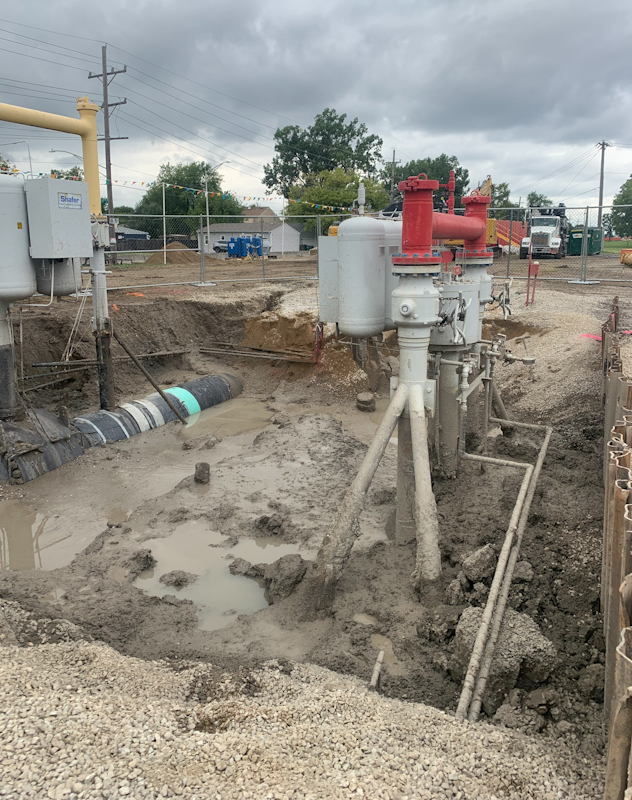
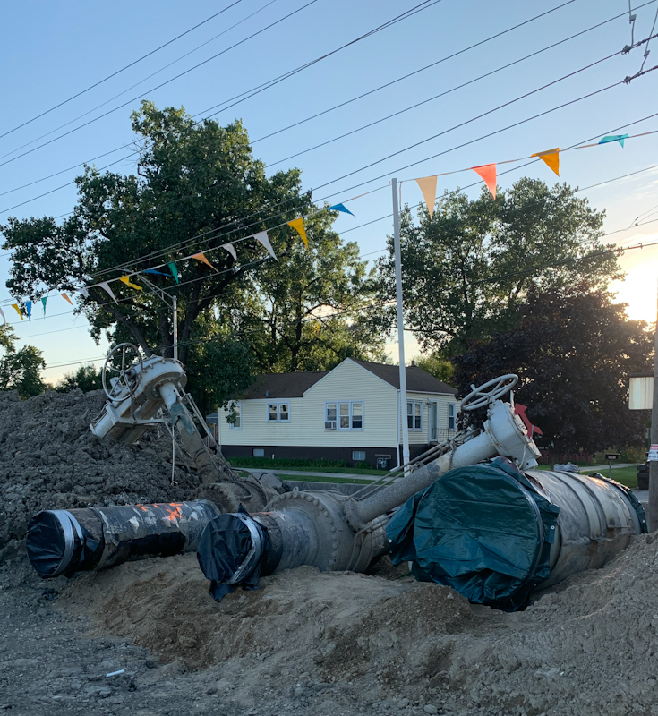
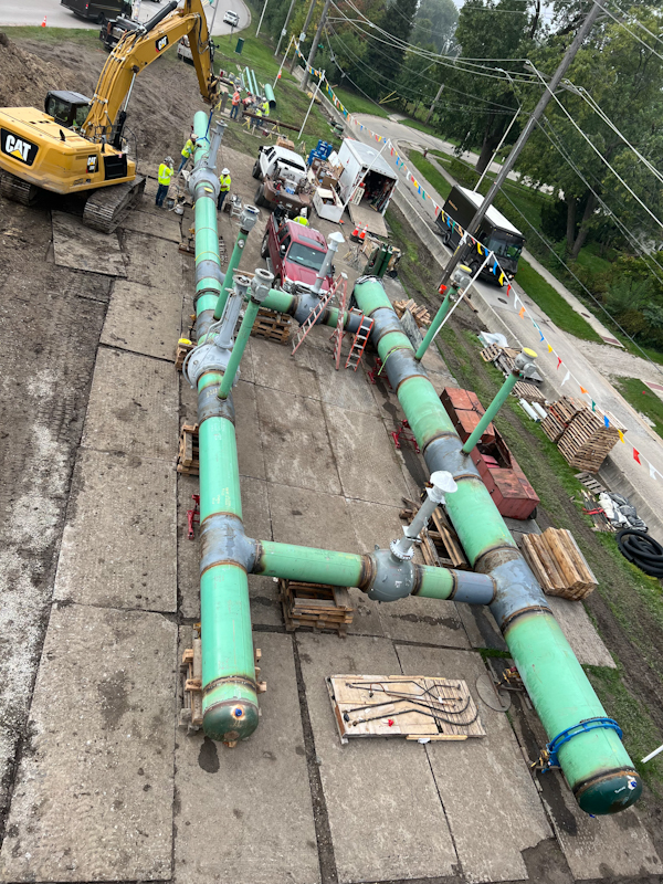
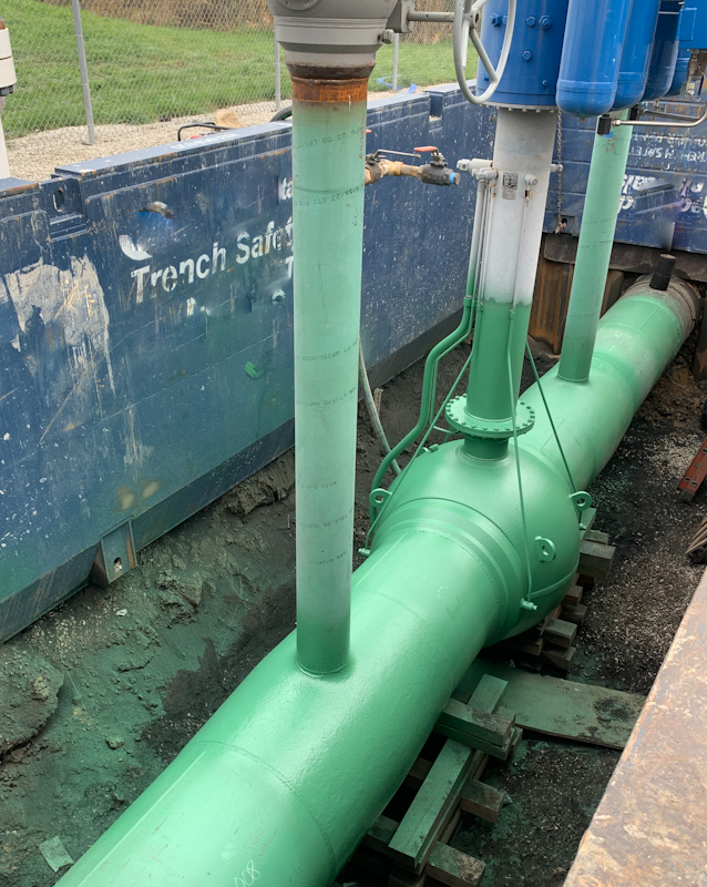
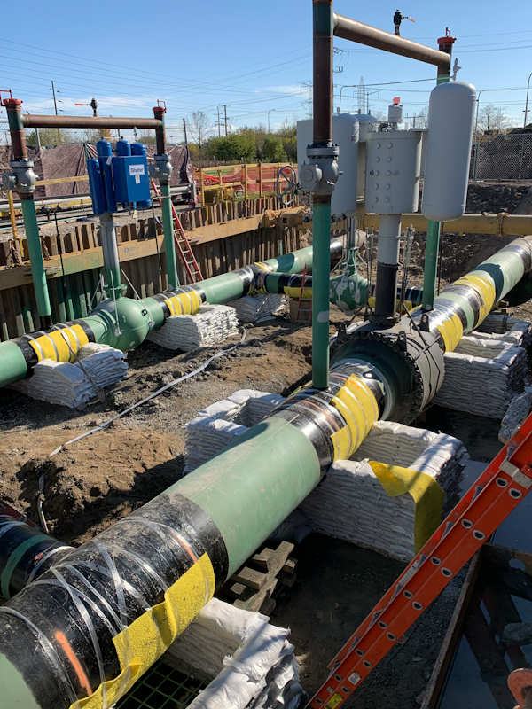
Midwestern Contractors provides construction services to gas companies when maintenance or upgrades are required. In this project a block valve site contained 30 inch and a 42-inch pipelines with cross over connections, valves, and valve bypasses. High volumes of gas passed through these lines every year, especially during the winter heating season. The buried assembly contained bolted flange connections, valves, and valve actuators. After conducting an engineering analysis, the decision was made to excavate the entire assembly and replace it with welded connections and new valves. This approach also allowed for the application of new above and below ground coatings, rock shield, as well as new pipe and valve supports.
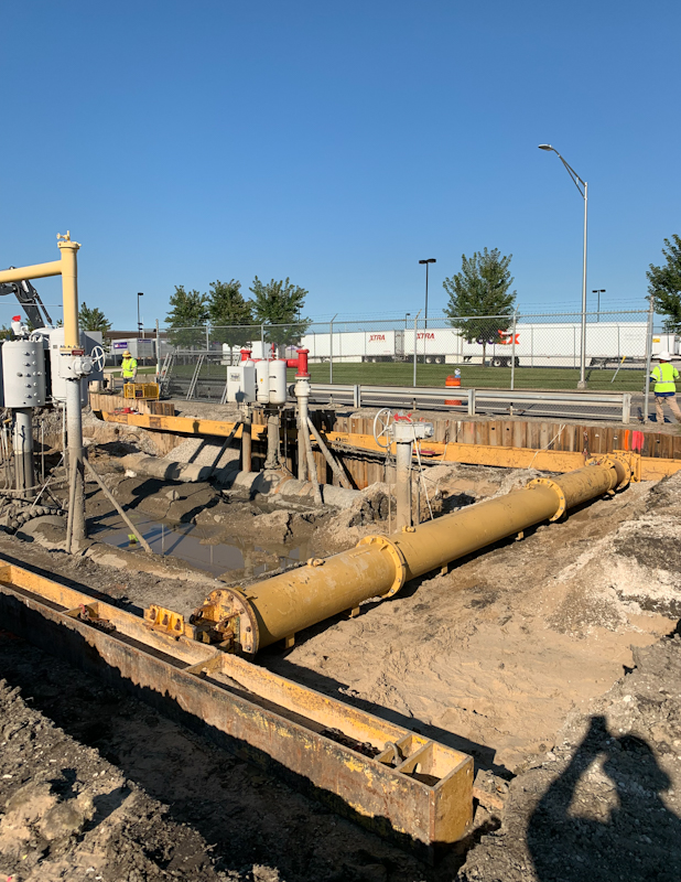
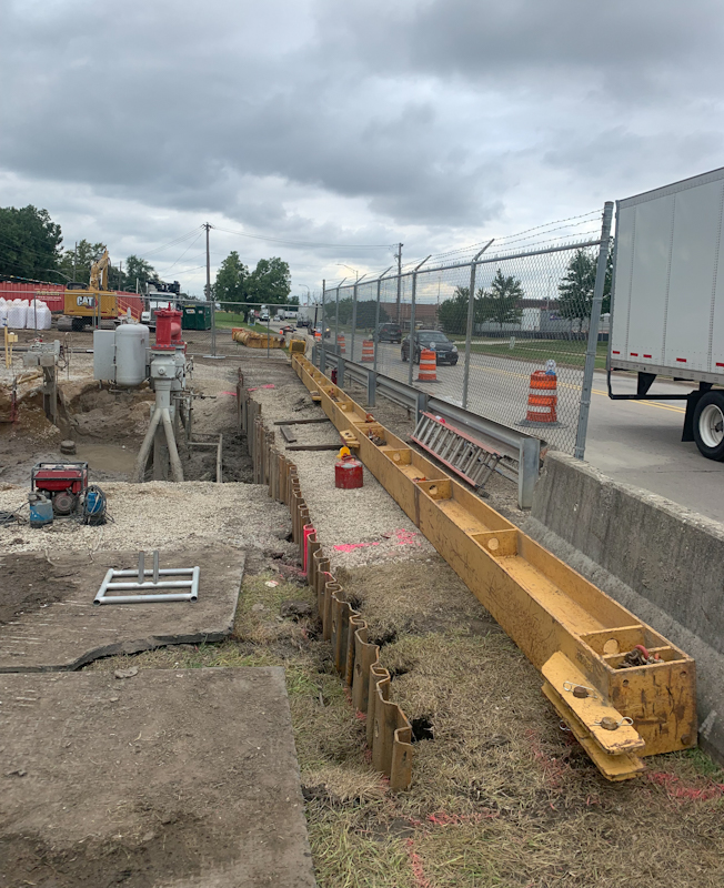
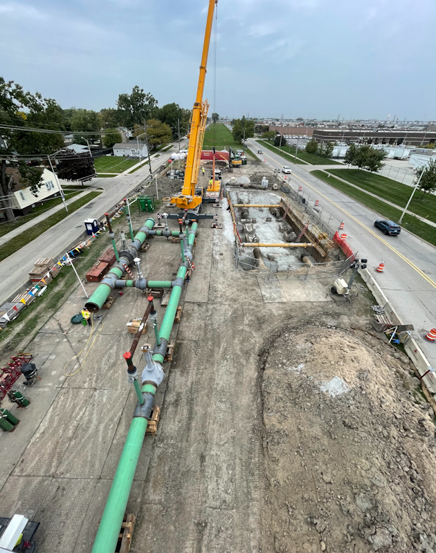
An adjacent highway and the loads imposed on it required an engineered shoring system to safely carry those loads through the excavation area. This shoring system consisted of a perimeter of sheet piling. The sides parallel to the highway received steel box beam, whalers. The rigidity of the whalers was such that only two hydraulic spreaders were required on each end. This allowed for the orderly demolition and removal of the existing crossover assembly and the subsequent installation of the newly fabricated replacement assembly.
SAFETY:
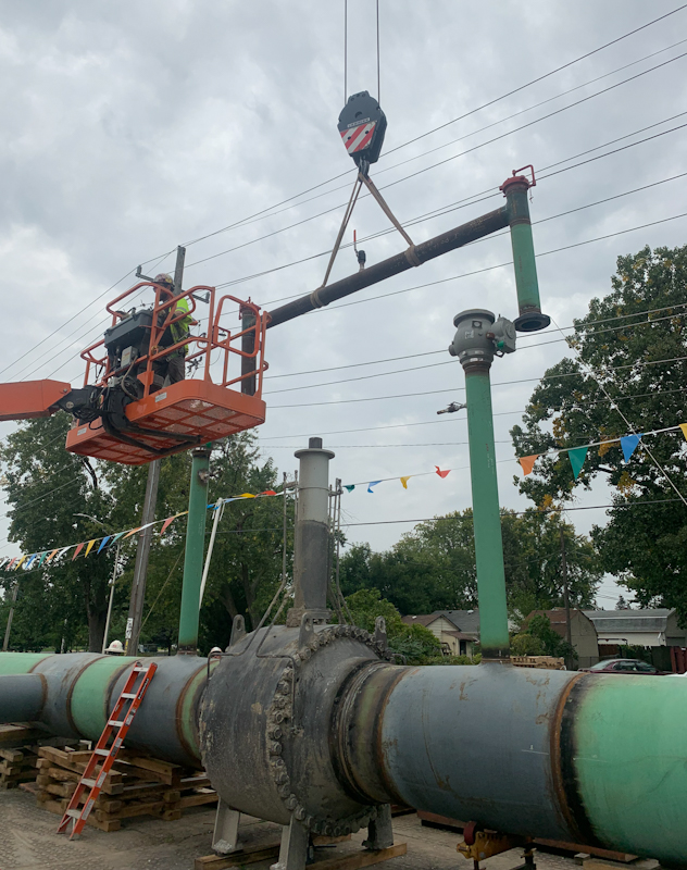
A constricted work area, sandwiched between two roads and bordered by 14 Kv power lines set up set the stage for the safety considerations on this project. In addition, a crane would be lifting and moving loads ranging from 10,000 to 85,000 lbs. The Safe Work Plan covered multiple hazards, including:
- Slip and trip hazards.
- Traffic safety, equipment movement, spotters, flaggers.
- Hazardous atmospheres, explosive atmospheres, LOTO plans, fire safety, fire watch.
- Electrical hazards, minimum approach distances (MAD), induced current.
- Line of fire areas, high potential energy sources
- Trench safety
- Lift plans
Click on any picture to enlarge shoring slideshow
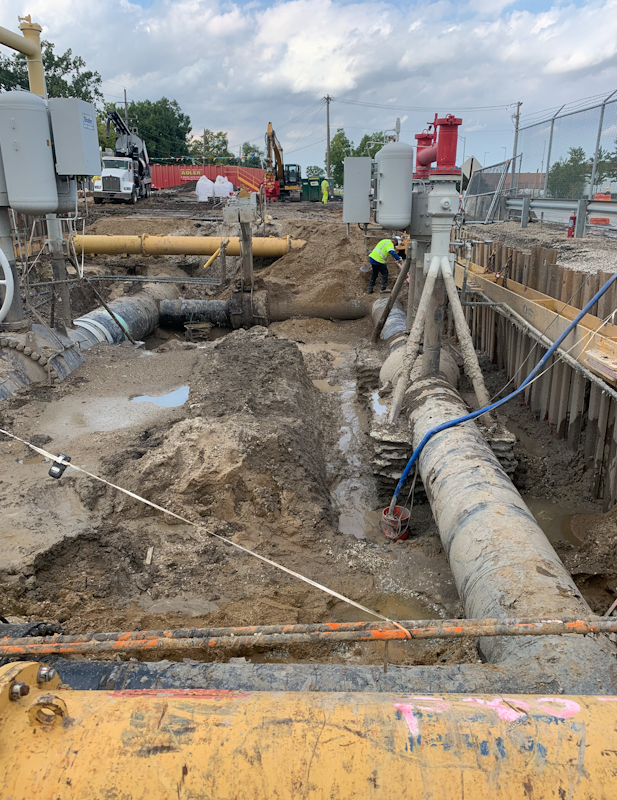
EXCAVATION:
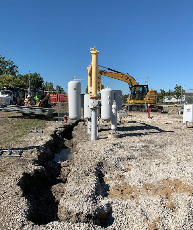
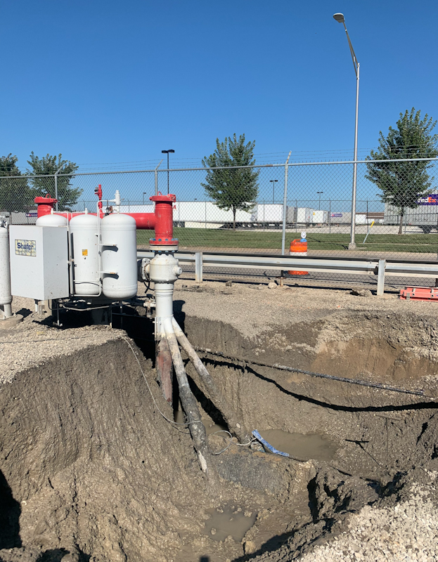
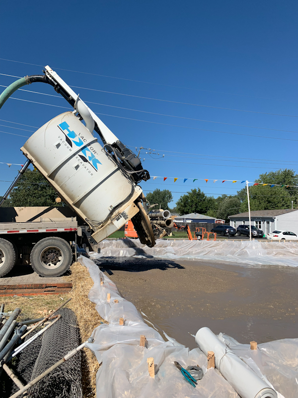
Hydro-excavation is safe to use around piping, electrical conduit, cables, and other underground utilities that would otherwise be damaged by mechanical excavators. This method also turns the spoils into a slurry that landfills will not accept. A containment area was built to hold the spoils until they could be solidified by using corncobs as an additive to absorb the moisture. With the moisture level reduced the spoils could then be transported to a disposal area.
Hydro-excavation is slow. On this project the hydro-excavation was utilized anywhere there was concern about damage to the piping. To remove the maximum amount of material in the shortest time mechanical excavation was employed wherever possible.
Toolbox talks emphasized the situation each day and changed with each phase of construction. Part of the safety mitigation challenge was the constricted nature of the work area. The coordination of tasks, equipment movement and material delivery required planning and is a testimony to the skill of our foreman on this project.
SITE PREPARATION:
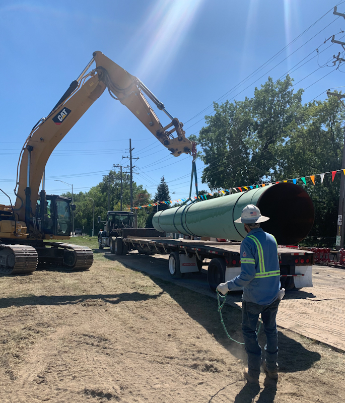
Traffic control was set to allow the safe movement of construction traffic into and out of the work area. Spotter and flaggers were employed to stop traffic and guide in lowboys loaded with equipment and trucks bringing material to the site as well as hauling spoils and demolished pipe off the site. The site offered no room for parking or staging. All loads had to be sequenced and coordinated. For example, as the fabrication was built the pipe and fittings were delivered as needed, then welded into place to make room for the next delivery.
Spoil hauling was closely coordinated since there was limited room for spoil storage onsite. Limits of Disturbance were defined, and spoil drainage and storage areas were delineated.
Electric distribution, 14 Kv power lines ran along one side of the work areas. This warning signage was installed at the jobsite and safe passage areas were defined with goal posts and colored flagging.
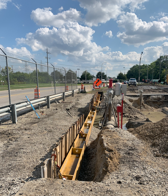
SHORING:
Once the perimeter of the excavation was established locates were called to identify all crossing utilities. Hydro-excavation was used to identify all utilities. With a now clear perimeter sheet piling was driven using a vibrating pile driver attached to a 300 series track hoe. The hydro-excavator removed approximately 24 inches of material, providing enough clearance to set the whalers and connect the hydraulic spreaders. Once set, the spreaders and whalers stabilized the walls of the excavation, and all material could then be removed. The process was reversed by backfilling and compacting.
"We worked with the United Rental team to design an engineered shoring system. The final design provided an opening large enough to lower the entire assembly into place. This minimized the number of tie-in welds. The box beam whalers and mega-spreader shoring system also reduced down time for our customer."
Graham Johnson, Project Manager


Click on any picture to enlarge excavation slideshow
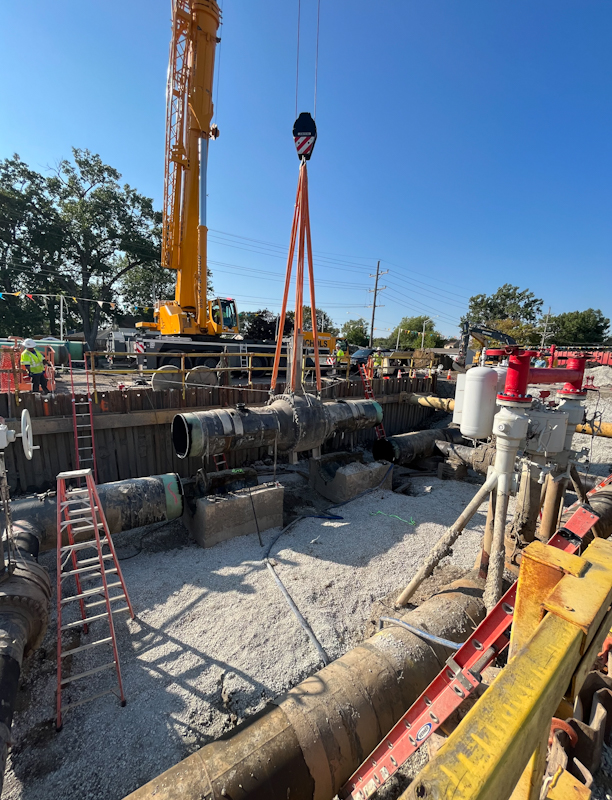
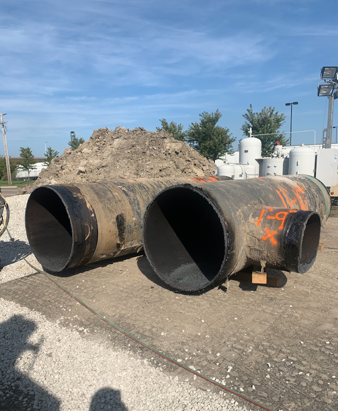
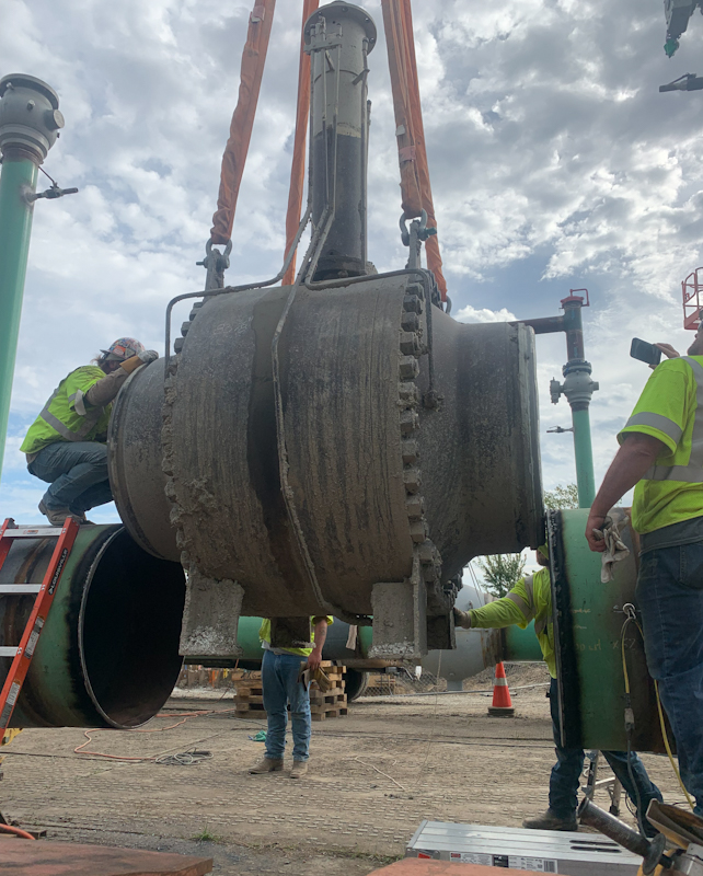
DEMOLITION:
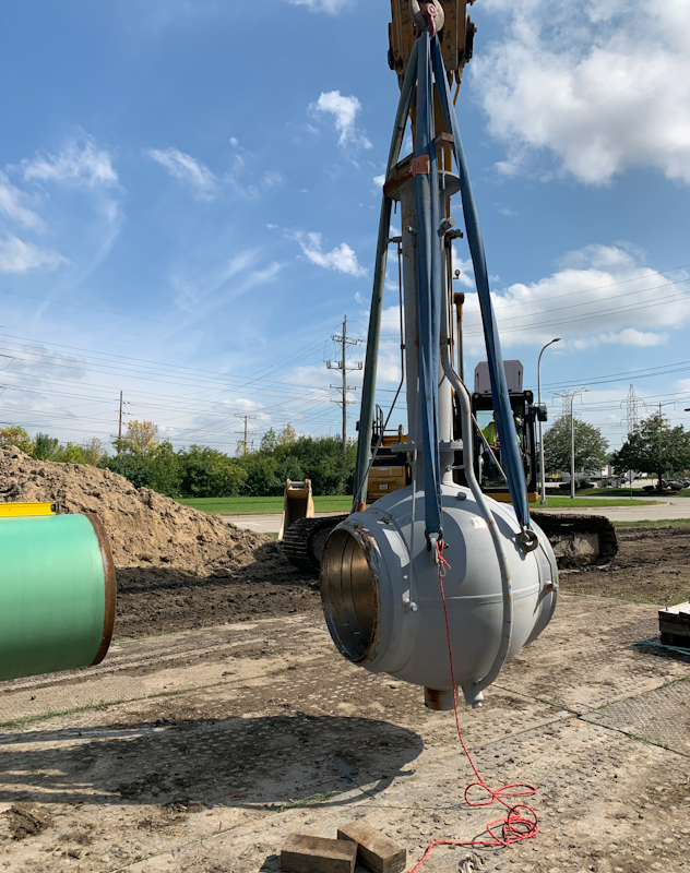
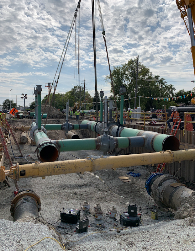
The system was blown down and went under lock-out-tag-out (LOTO). Air movers were placed to evacuate any gas in the system. At this point demolition was started. Valve actuators were removed, then piping sections containing the large 30- and 42-inch valves were removed first. These segments weighed in at 15,000 and 35,000 lbs. respectively. A crane was carefully positioned away from power lines and rigged to hoist these loads. Coating was stripped away from the pipe and hot cuts were made to sever the pipe and valve. This process was repeated for all the 30-inch and 42-inch pipe as well as the cross over piping and all actuators. Each segment easily cleared the shoring system. The pipe ends were wrapped, and the segments were then loaded for transport to the scrap yard. Coating samples were analyzed for asbestos. All small diameter sensing piping was removed as well.

Click on any picture to see demolition slide show
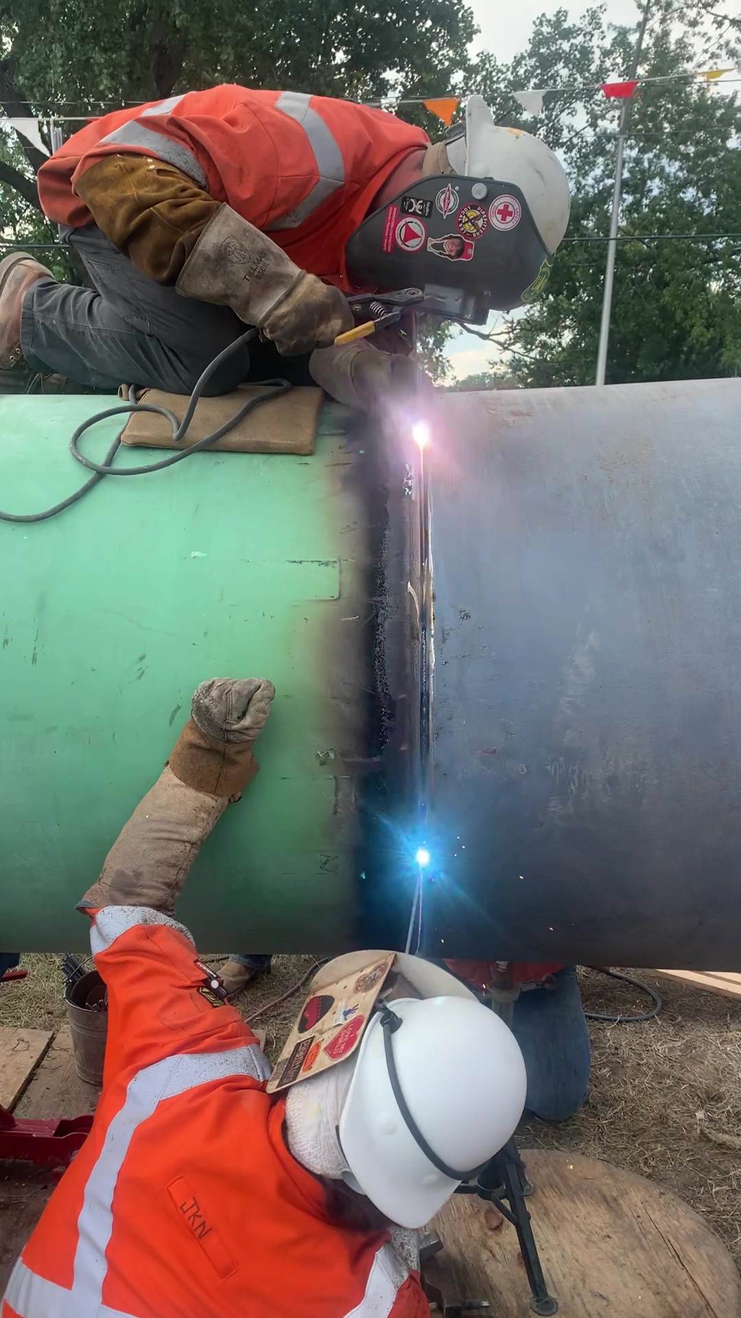
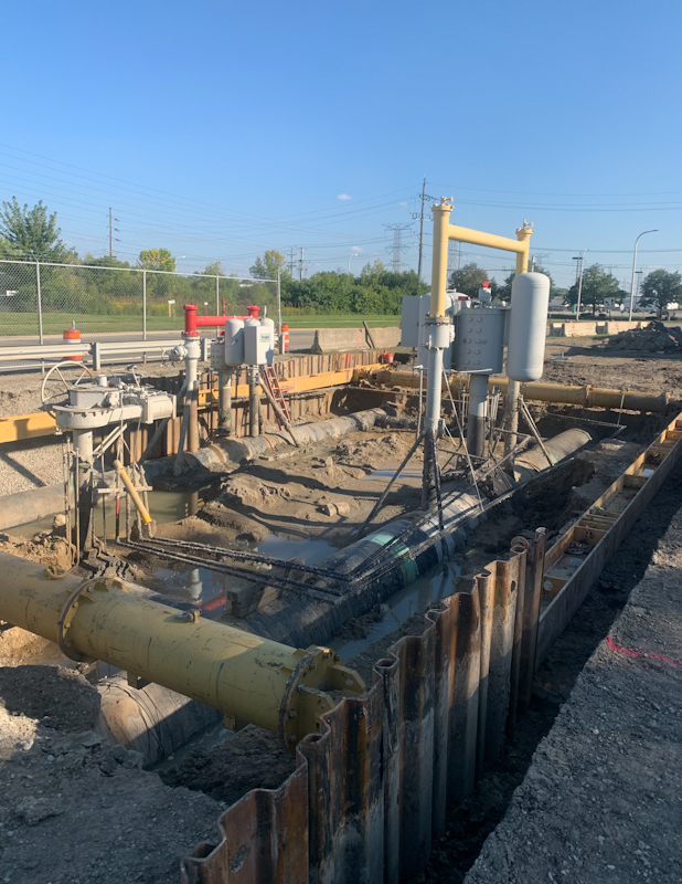
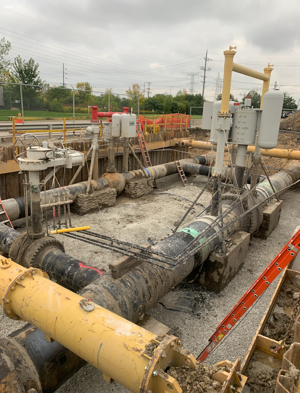
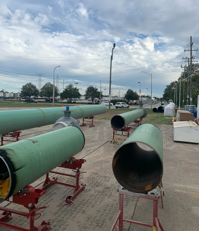
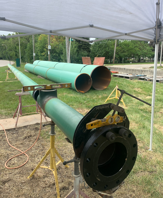
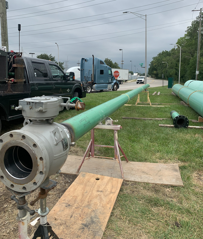
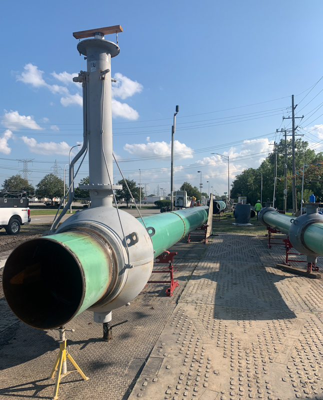
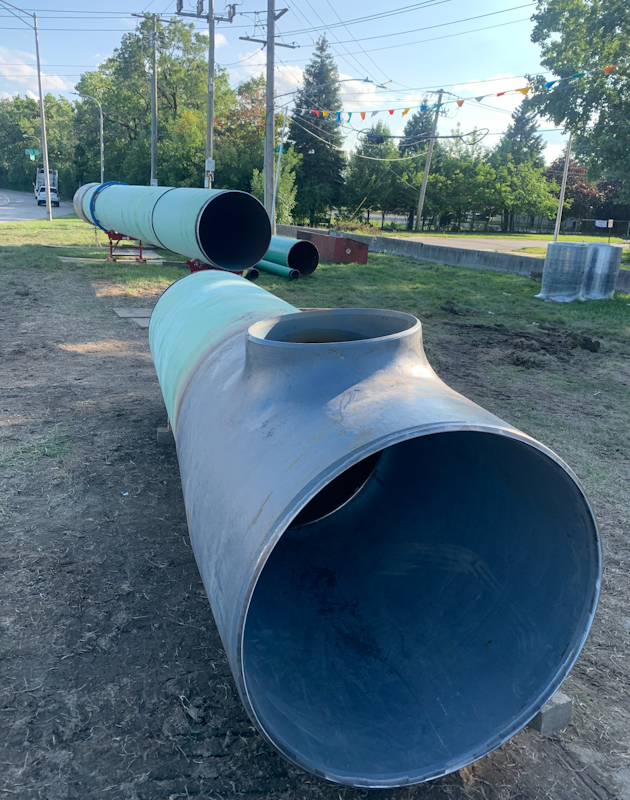
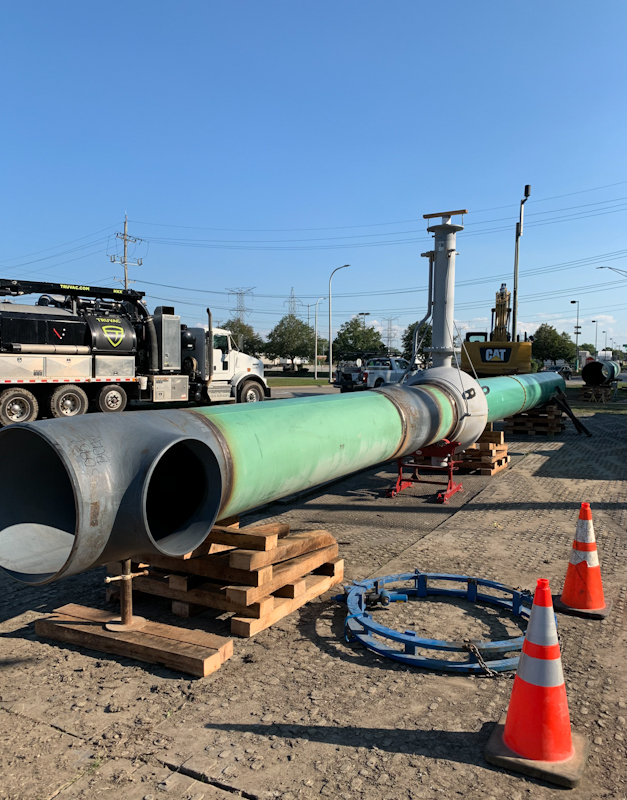
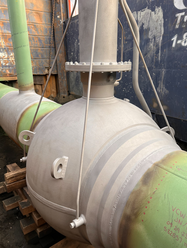
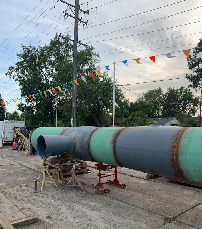
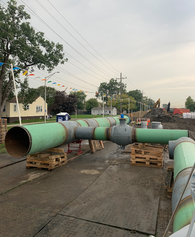
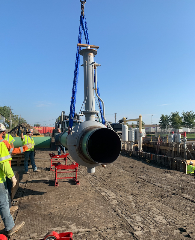
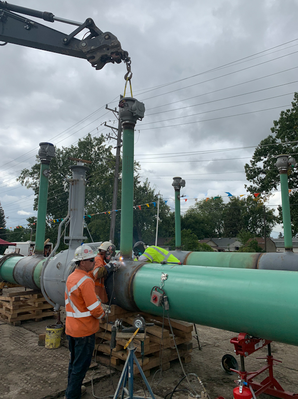
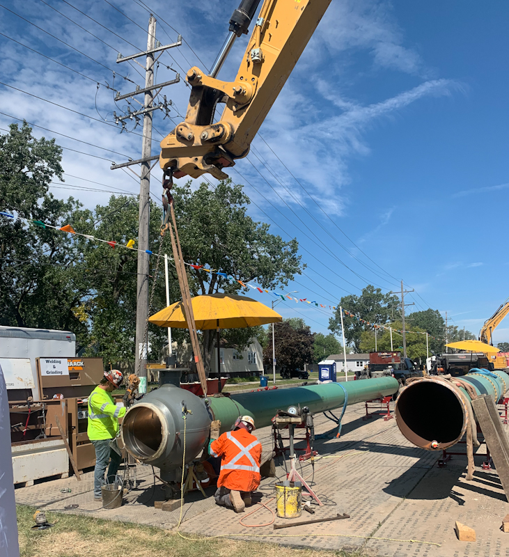
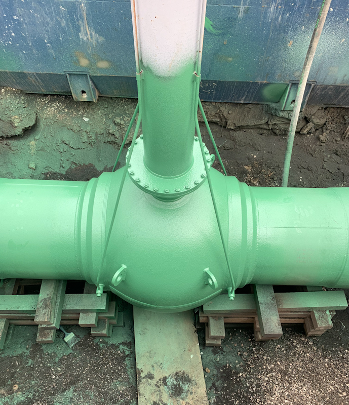
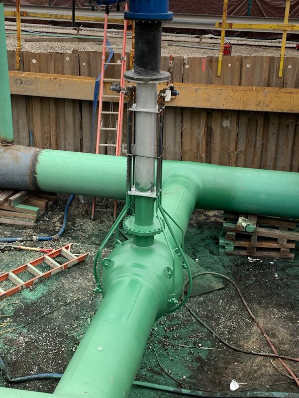
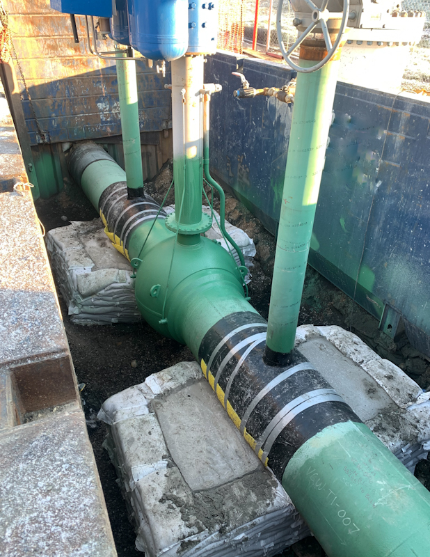
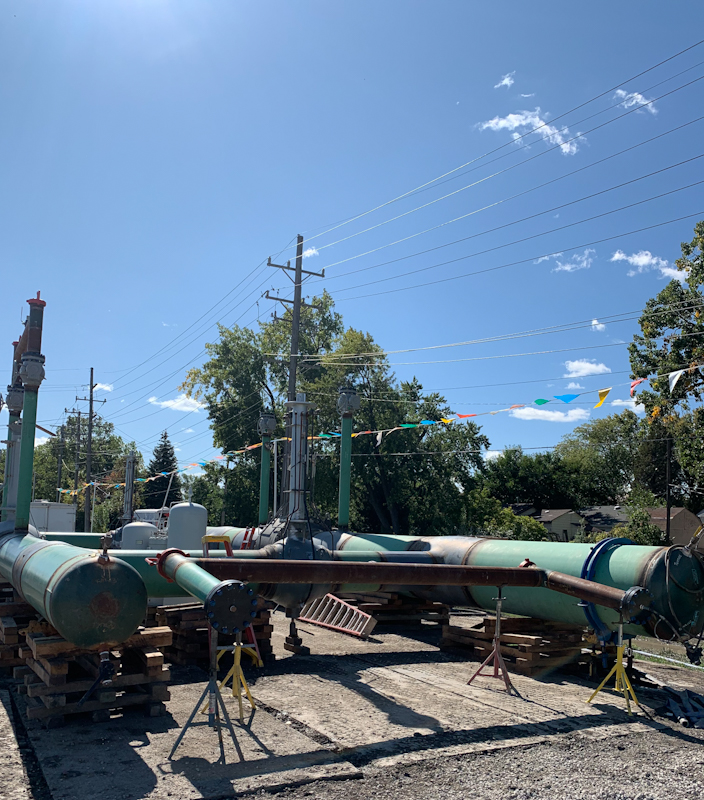
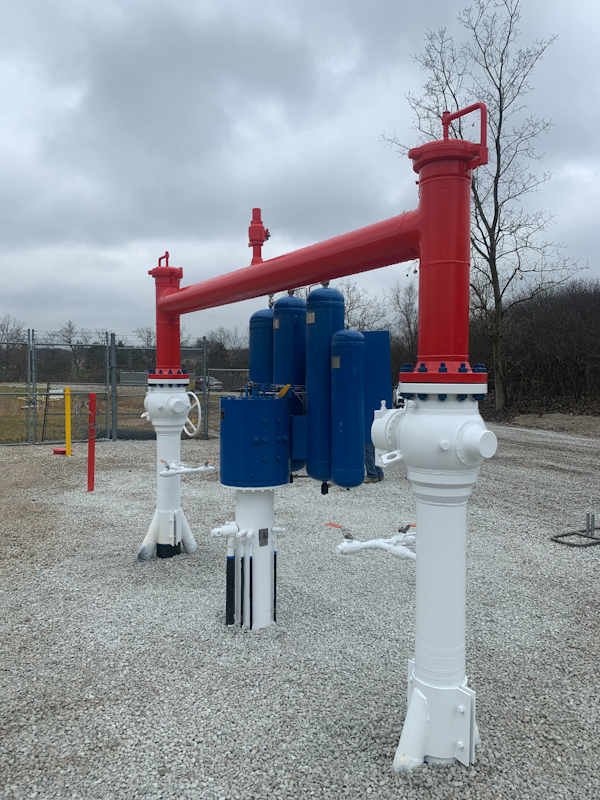
FABRICATION:
At the same time the demolition was occurring, the welders and fitters were building the new assembly. The valves were welded to the main 30-inch and 42-inch pipes. T’s were then fitted and welded, both sides were welded together with crossover piping. Valve stem pipes, bypass piping, and TORs were added. The final assembly weighed in at approximately 85,000 lbs. and was designed to be installed as a unit to cut down on tie-in welds. The entire assembly was hand built and had to be made to match up with the existing pipes. A small pup piece was utilized on one side to allow for tie-in. The assembly fit perfectly.
Click on any picture to see fabrication slideshow
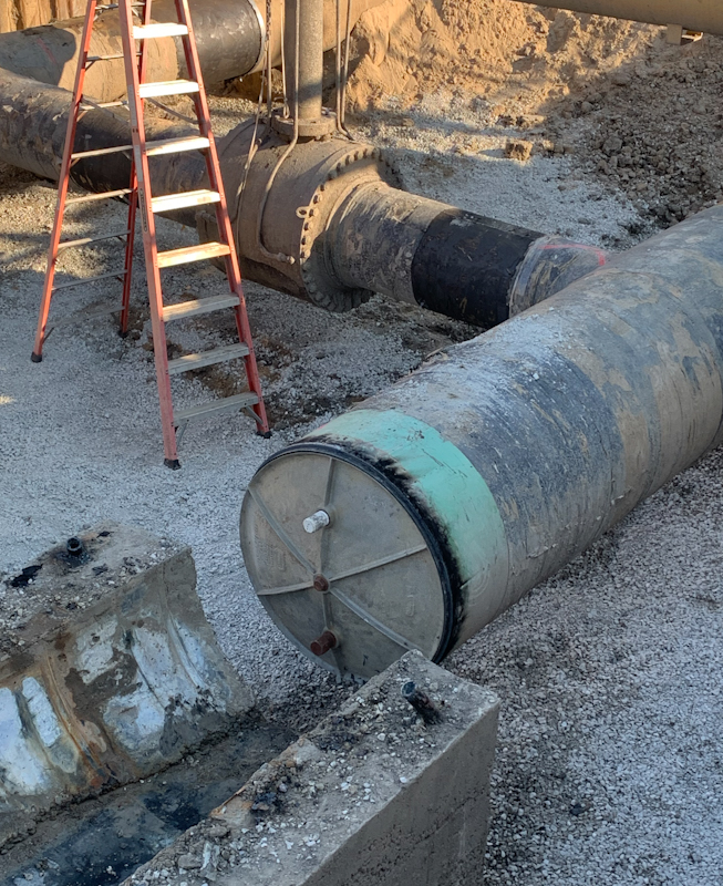
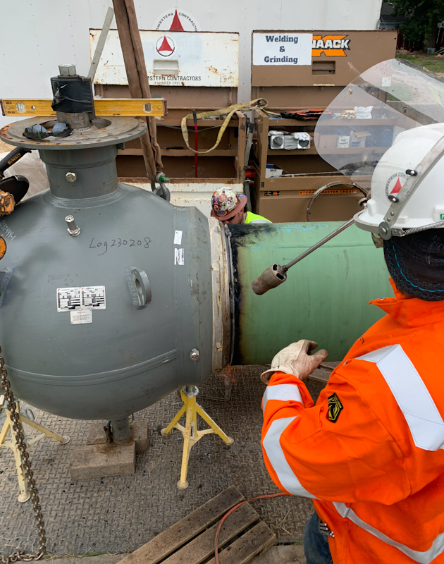
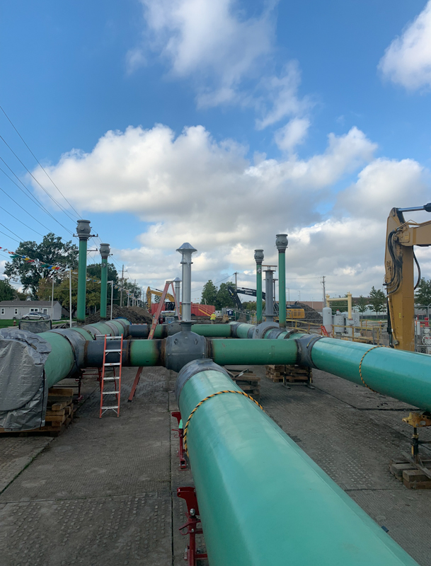
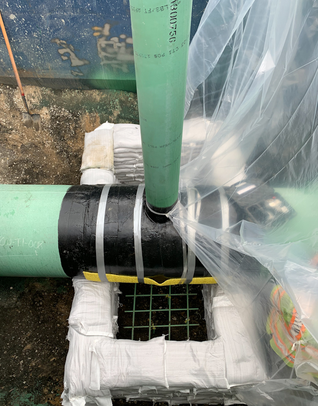
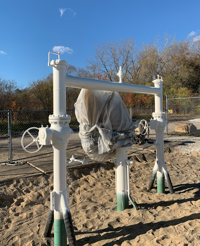
COATING:
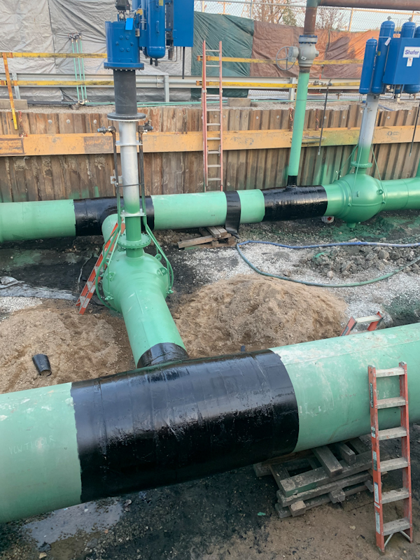
Coating is an extremely important, but underappreciated, part of any underground pipe installation. Coatings of distinct types protect the pipe from abrasion, oxidation, and stray dc voltage running underground. The piping was coated at the factory, but all welds, valves and fittings required coating. The first step to achieve a bonding surface by sand blasting the surface to near white. The surface profile is measured to be sure it meets specification, then the epoxy coating is applied. DENSO 7200 was applied using preheated spray cartridges. Proper application using these cartridges yields a smooth coating of uniform thickness.
As the fall ended and temperature dropped, the remaining fittings were shrouded to maintain a higher temperature. This allowed the coating to cure. All coating was measured for thickness. In areas where the pipe would bear on supports the pipe was coated with hot wrap and rock shield to create additional protection for the pipe. On the bypass piping and other parts that protruded above grade the air/ground transition area was treated by extending the epoxy coating above ground, overlapping the paint coating, and then overlaying protective woven fiberglass material around the pipe and overcoating it. This protects the pipe from abrasion at the surface.
Click on any picture to enlarge coating slideshow
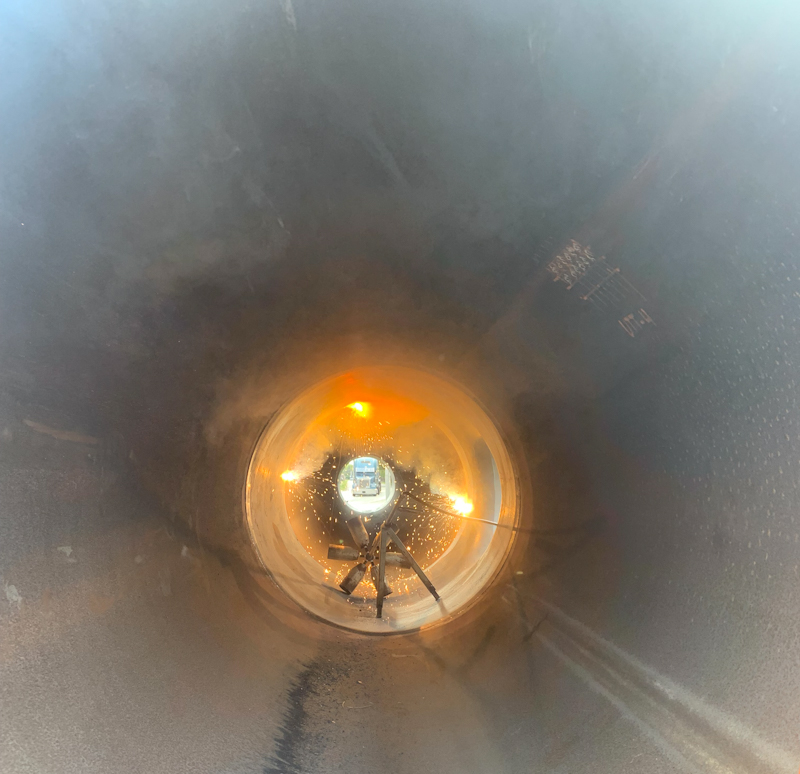
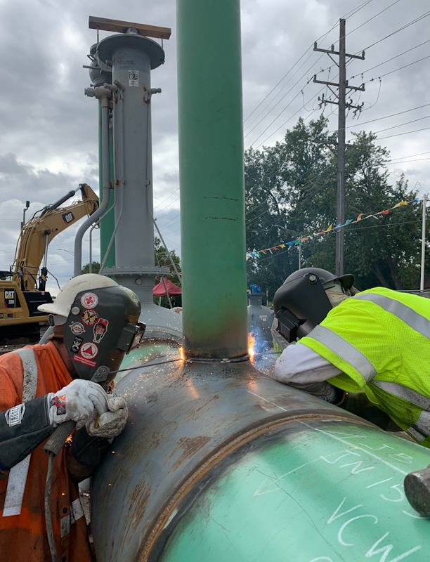
HYDROSTATIC TESTING & NDT:
As the assembly was welded each weld was x-rayed to check for imperfections in the welded joint. Large diameter pipe requires preheating and multiple welders simultaneously welding on each pass to distribute the heat evenly and prevent stress cracking. On this project all welds were x-rayed down to the two-inch sensing piping. This level of non-destructive testing (NDT) is another way of assuring the quality of the welding, and by extension, the life of the project.
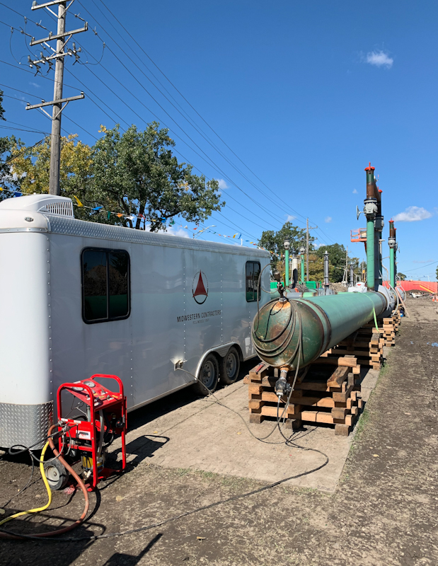
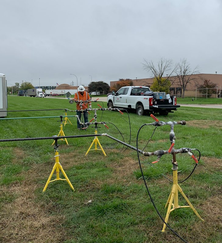
The last step to assure the assembly will hold pressure is to hydrostatically test it to 1.5 times the maximum operating pressure (MAOP). Midwestern Contractors uses a purpose-built test trailer to conduct these tests. This climate-controlled trailer has its own power, water tank, high pressure pumps, fittings, test recorder, and deadweights, everything necessary to conduct hours long tests. The test area was cordoned off and the test was conducted successfully. The gas sensing piping was nitrogen tested.
Click on any picture to see hydrostatic testing slideshow
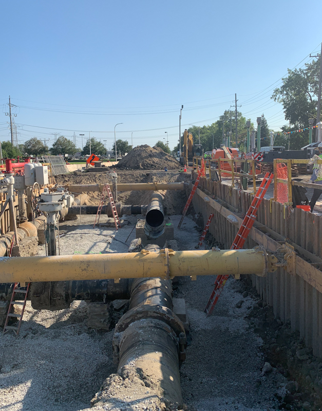
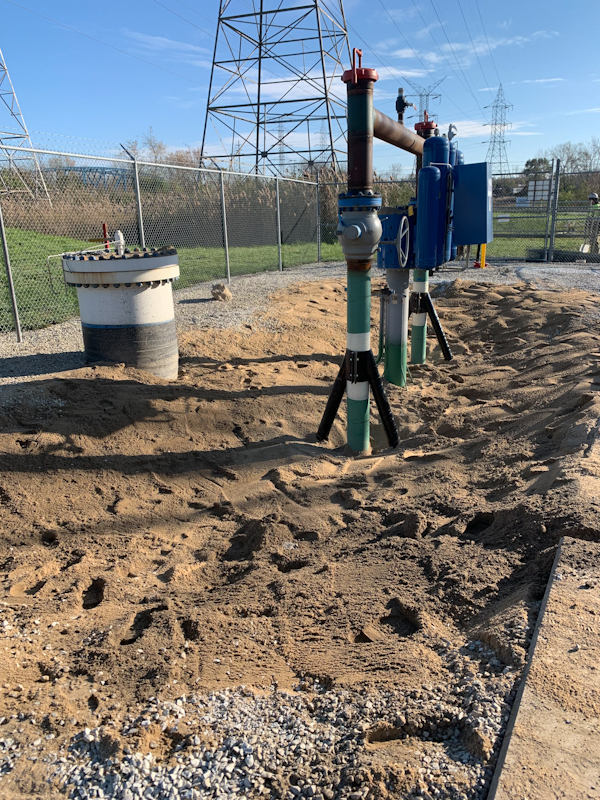
BACKFILLING & COMPACTION:
The entire assembly was set on formed and poured pipe supports. One foot of sand padding was added around the pipe. Soil was then used for backfilling, and it was compacted in one-foot lifts.
SHORING REMOVAL & CLEAN UP:
Once the excavation was backfilled to the level of the whalers the internal bracing could be removed. The hydraulic spreaders were lifted out, then the whalers. After this was completed the sheet piling was removed and stacked neatly for transport off the site.
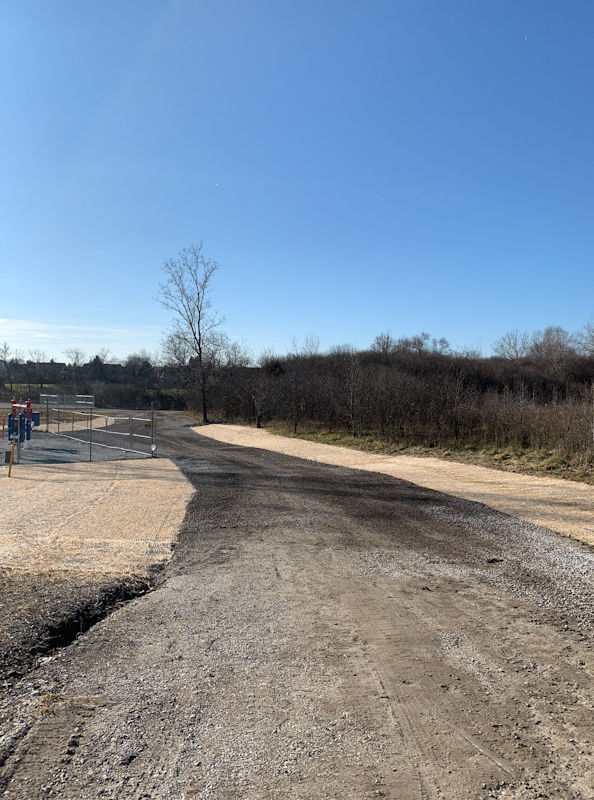
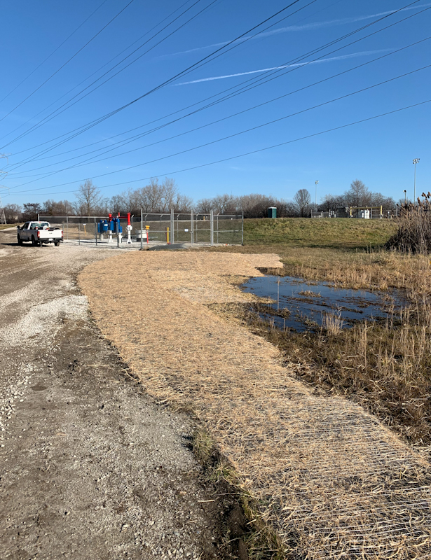
Finally, the site was cleaned up, geo-textile fabric and gravel spread on the surface, and the perimeter fenced. The site was delivered, complete, to the customer.
Project Summary
Excavation size 30,000 ft³
Welds 250 on diameters from 2” to 42”
Paint 2-part system Sherwin Williams
Hydrostatic test on main assembly 8 hour
Nitrogen test on gas power piping
Project duration 90 days
Safety incidents Zero
Recordables Zero
Click on any picture to see backfill and completion slideshow
Documentation:
Projects such as this one requires detailed documentation of every aspect of the work and the permissions to perform the work. Here are few of the types of documents that must be tracked and archived: All types of permits, including traffic, excavation, hot work; MTR’s and heat numbers on all steel pipe and fittings, sand blast profile checks, coating mil thickness, weld x-rays, welder test qualifications, weld maps; rigging certification, crane certification; Hydrostatic test equipment calibration reports, test charts; Compaction tests, as-built drawings, worker OQ’s and photographs.
This information along with drawings and construction specification are contained in our cloud-based project management system called Construction View. This system is accessible by project managers, foremen, operations personnel, and management. It is an encrypted, cloud-based system that serves to contain and archive this type of information.
About Midwestern Contractors:
For over 70 years Midwestern Contractors has provided project management and construction services to the oil and gas industry. The company has grown and along with its parent Electric Conduit Construction, now serves the following industries: oil, gas, industrial gas, renewable gas, fiber optic, telco, overhead and underground utility placement, industrial electrical. This broad range of services allows the companies to deliver turn-key projects that require installation of piping, communications, electrical and fiber systems. We welcome your interest in our company and look forward to bidding on your projects. Please click on “Project Request” and one of our project managers will respond.