Installation of Small Volume Provers
Companies buy, sell and transport millions of barrels of oil and refined products every day. With each exchange there is a requirement for accurate measurement of the volume of product sold. A common device used for measurement is the rotary vane meter. This style of meter measures the flow rate, from which a flow computer calculates the number of barrels of product per unit of time.
Like any mechanical device, a meter will wear over time and the accuracy will degrade – external conditions (temperature, low or high flow, etc.) can cause deviations in accuracy as well. To compensate for this, companies use a prover to verify the meter’s accuracy – this function has earned provers the nickname “the cash registers of the pipeline.” In its simplest form, a prover is a container of known volume. At the beginning of every new batch that is pumped through a pipeline segment, the prover is filled, and the volume measured by the meter during this operation is compared to the known volume of the prover. These two volumes are used to generate what is known as a “meter factor” to ensure the meter is accurately counting flow through it for the duration of the batch.
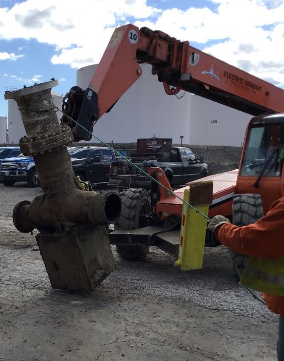
Oil companies originally built provers in the form of long U-shaped pipes, which were fabricated to precise volume. These provers were made in both single and bi-directional configurations and known as “ball provers” because they used stiff rubber balls to move the liquid through the prover.
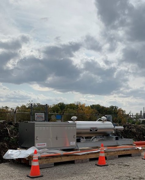
In recent years, Small Volume Prover (SVP) have replaced these large ball provers. These devices use the same principle of a known volume, but instead of using a large volume cycled once (often 25-50 barrels), an exceedingly small volume (usually no more than 1-2 barrels) is cycled repeatedly and measured very precisely to achieve a level of accuracy that will satisfy the standards set by organizations such as NIST. Diane Lee has written extensively on this topic and here are links to her articles:
https://www.nist.gov/system/files/documents/2017/05/09/H-003.pdf
https://www.nist.gov/system/files/documents/2017/05/09/H-004.pdf
https://www.nist.gov/system/files/documents/2017/05/09/H-007.pdf
https://www.nist.gov/system/files/documents/2017/05/09/H-010.pdf
https://www.nist.gov/system/files/documents/2017/05/09/H-012.pdf
Understanding how a prover functions helps us do a better job of building the infrastructure that supports the unit and the piping that feeds it.
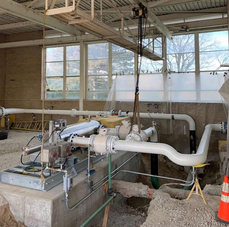
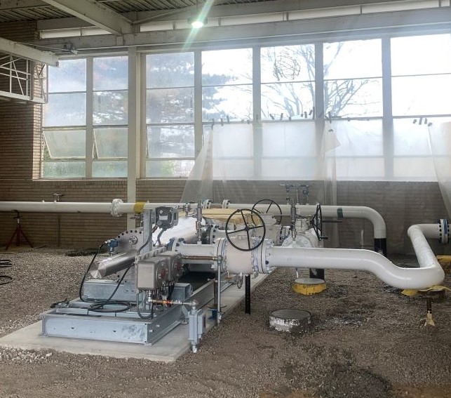
Midwestern Contractors (MWC) has completed turnkey, 100% self-performed installations of one or two SVP’s each year for the last six years. SVPs are precision instruments, and they are also more accurate and efficient than ball provers.
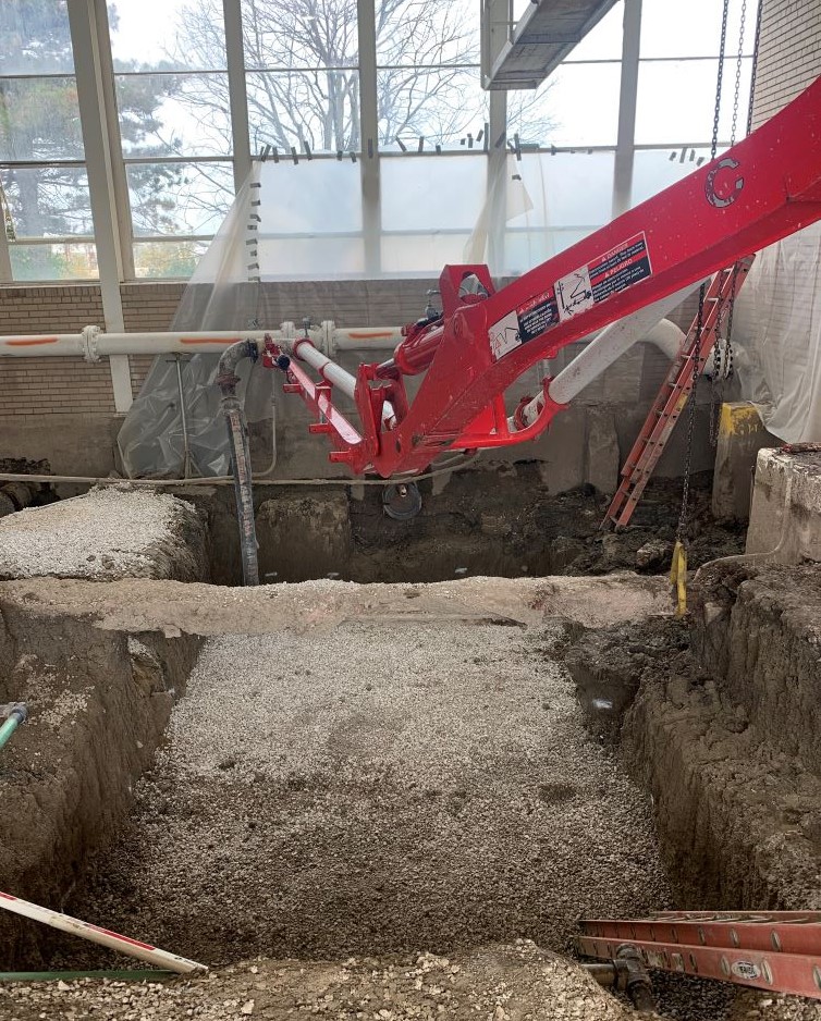
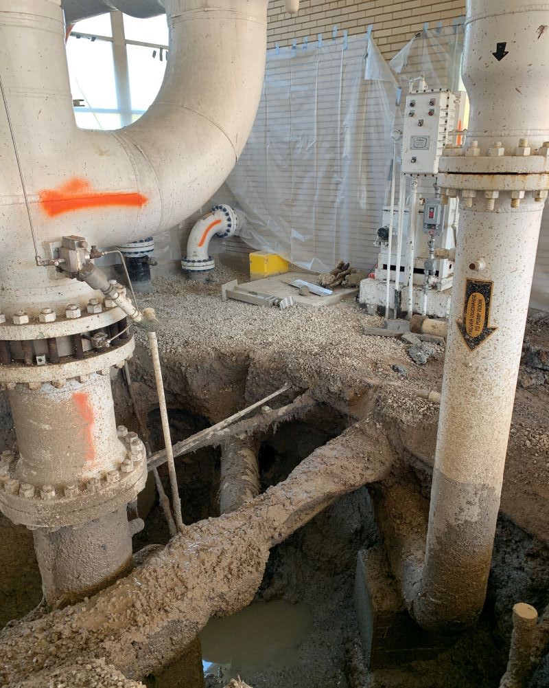
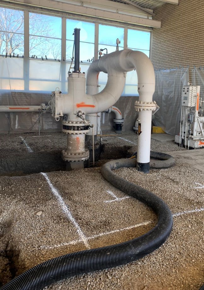
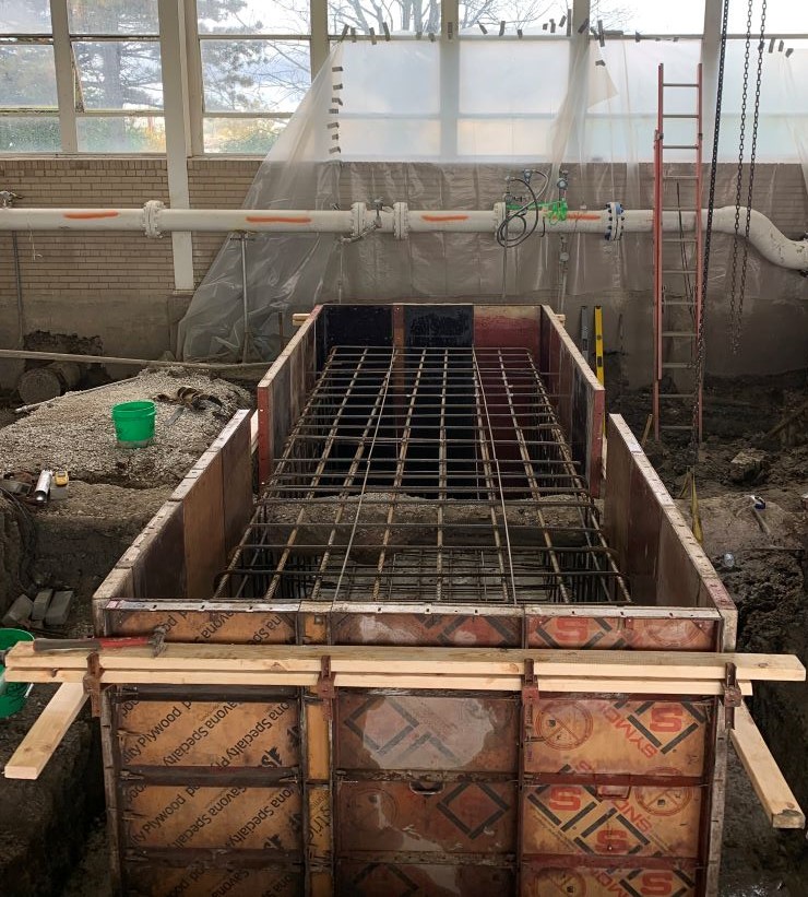
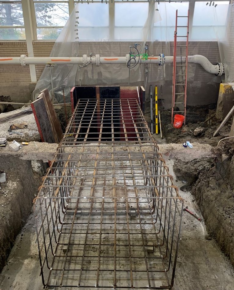
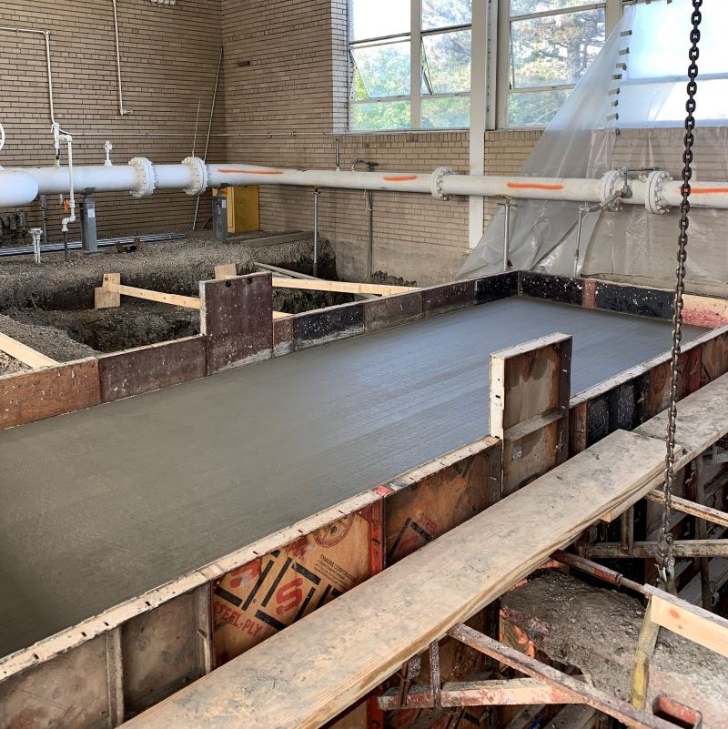
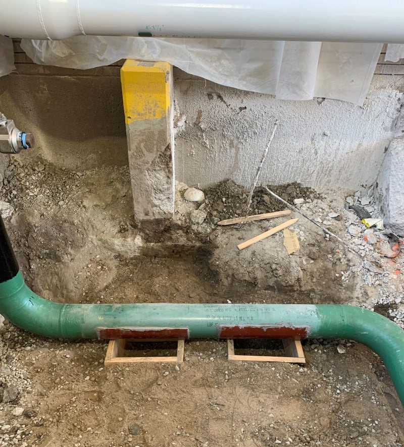
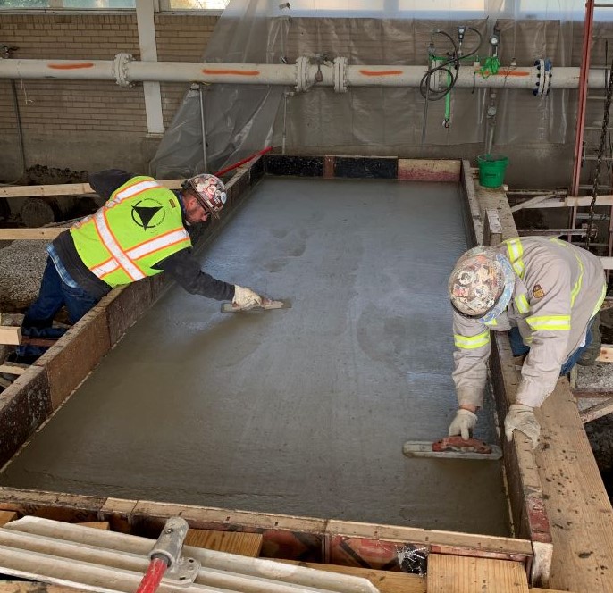
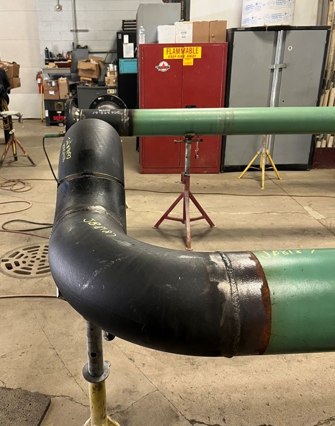
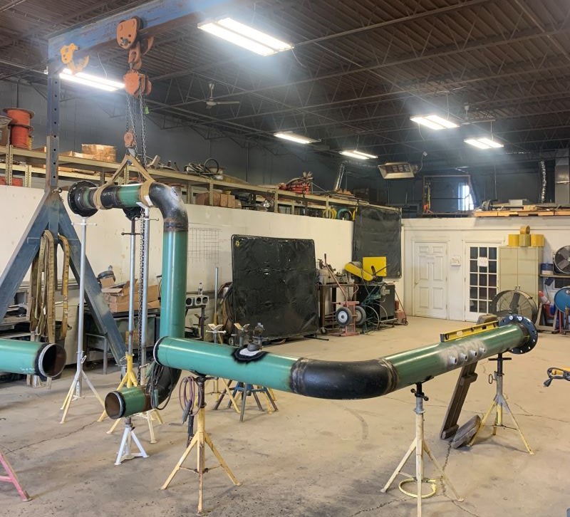
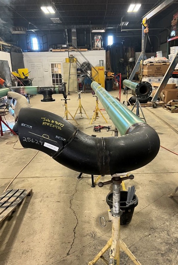
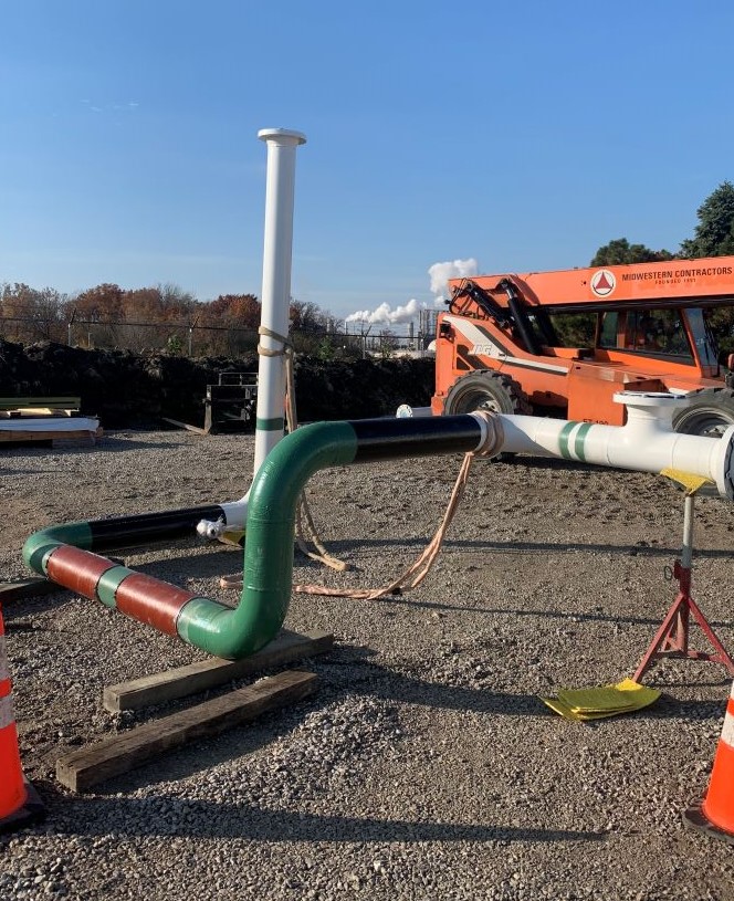
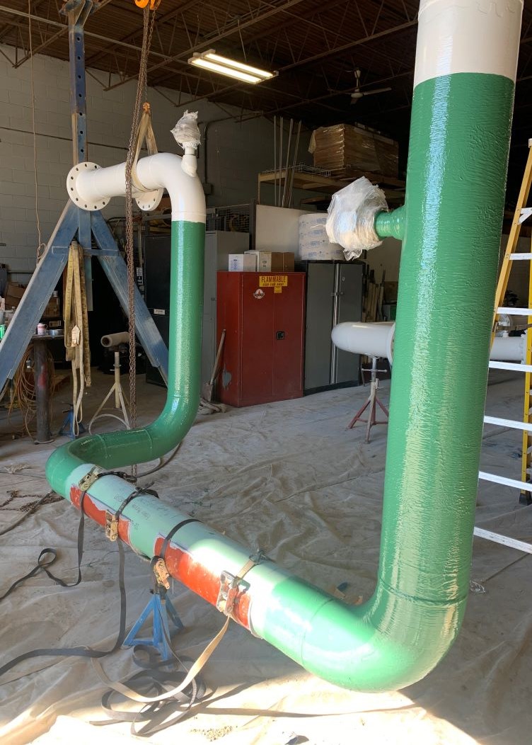
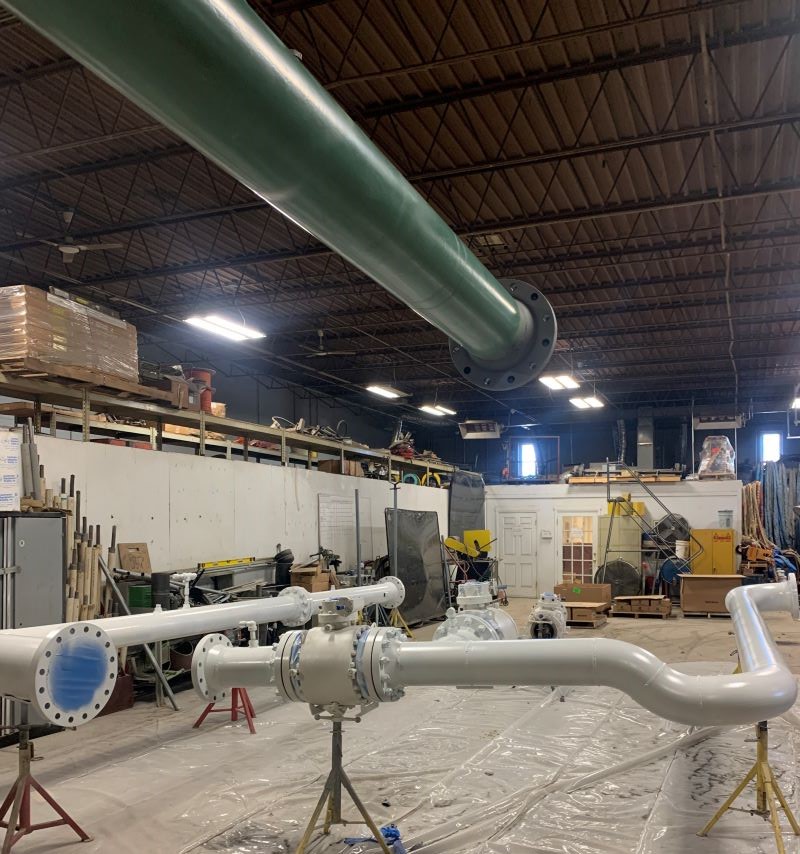
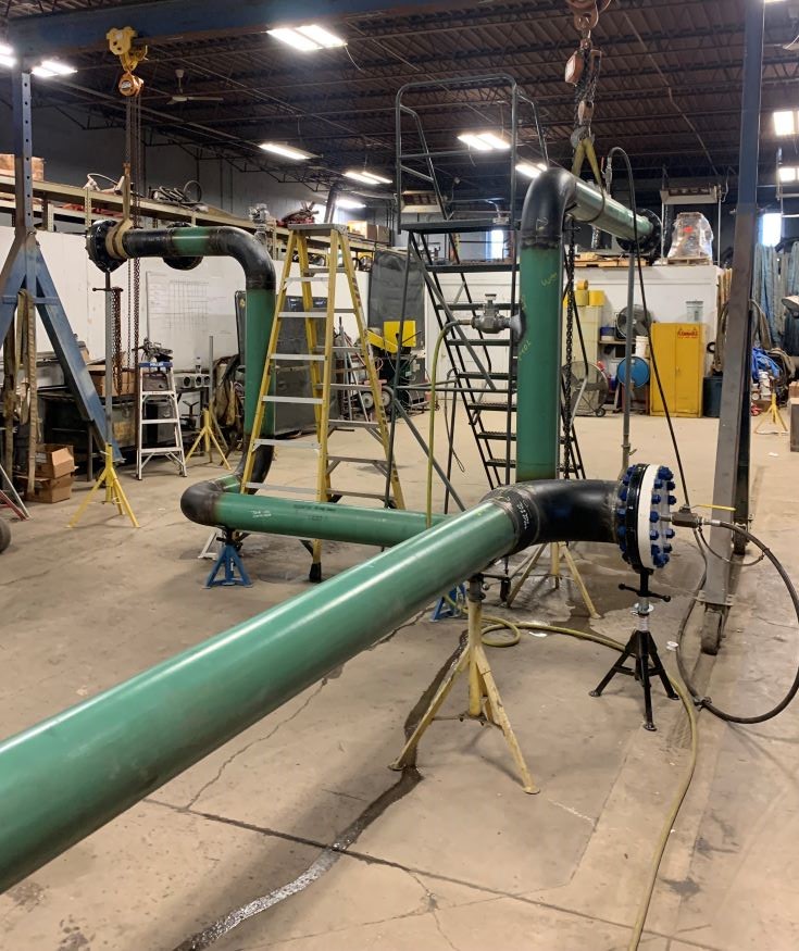
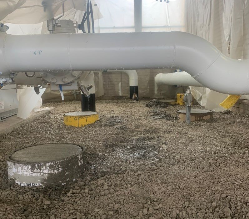
New SVP installations require demolishing that the old prover and associated piping & foundations. Once this is done, the first step is to establish the new piping tie-in points and new prover foundation location. A civil crew then excavates for the foundation, installs reinforcing bar, and pours concrete. Prover foundations are often large, monolithic blocks of concrete, or sometimes they are mounted on steel frames set on concrete pillars. Foundations are also poured to provide support to the piping and prevent it from stressing the connections on the prover – stress on the prover connections can affect accuracy and cause prover failure. Samples of the concrete are taken during the pour and tested for compressive strength to ensure the new foundation will last for its design life. Once the concrete has cured enough to allow it to be loaded with the weight of the prover, the prover is set on the foundations and fitters can take hard measurements for the new piping. Between the inlet and outlet piping on the prover is a bypass line which allows product flow to past the prover without entering it – this is important for maintenance purposes. Once measurements are taken, welders begin fabricating the piping that will allow product to enter and leave the small volume prover. After fabrication, every butt weld must be non-destructively tested by X-ray and every fillet weld non-destructively tested by magnetic particle testing to make certain that they are sound, and no defects (or “inclusions”) exist. The piping is then filled with water and pressurized to verify the integrity of the assembly in a process known as hydrostatic testing. This is followed by painting & coating to protect the piping from corrosion. The pipe is then installed. After installation, any below ground piping is backfilled with sand, leveled and covered with gravel to provide a walking surface for operations personnel.
A key part of a small volume prover installation is working with pipeline operations and the pipeline control center to ensure that the time between removing the old prover and installing the new prover is kept to a minimum, as pipeline accuracy is reduced during these periods. Historical meter factors can be used temporarily, but minimizing downtime is paramount. Midwestern Contractors has considerable experience optimizing the installation of small volume provers, saving customers time & money.
Project notes:
- 30 Yards of concrete
- 100 Tons of sand & gravel
- 100-200 Yards of spoil
- 25-50 Feet of x diameter pipe
- 250 +/- 100 Diameter inches of welding
- 480-volt power and associated control wiring
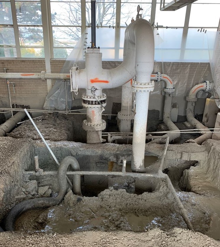
Due to the high concentration of underground pipes & conduits inside pipeline stations, hydroexcavation is often the preferred method of excavation. Occasionally, due to the age of many of these facilities surface contamination can be found. This often means that spoils need to be handled and disposed of in a special manner.
Companies usually install provers and then house them under a building or canopy. Removing the old equipment and piping and installing a small volume prover usually requires demolishing part the building and then replacing or repairing as needed.
Safety note:
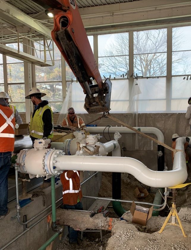
Projects inside existing facilities present a distinct set of hazards compared to greenfield projects. Usually, electrical power and control wire conduits, along with pressurized piping, occupy the subsurface area. A strike on one of these utilities would be extremely dangerous and would cause the foreman or crew to stop work.
After hydro-excavation movement in the work zone becomes hazardous. Working, moving, and lifting in these circumstances can lead to soft tissue injury and muscle strains. Workers can easily find themselves in the line of fire when work areas are this congested.
At MWC safety officers develop the Safe Work Plan with these hazards in mind. The foreman and crew review and adjust the plan daily to accommodate the circumstances that exist for the day’s work. We do not compromise when it comes to safety. Our history backs this up.
Summary:
Provers are necessary devices that accurately measure liquid volumes and assure the accuracy of meters. Their installation requires careful planning, skilled craftsmanship, diligence, and a dedication to safety.
About Midwestern Contractors:
MWC is a 70-year-old oil & gas contractor with an outstanding safety record. Projects include pipelines, stations, integrity work, pipeline relocations, laterals, pipeline extractions and lowering. Electrical work including industrial wiring, control wiring, and fiber optic cable, testing and termination. Civil work including grading, foundations, footings, surface, and ground water management. Environmental work including erosion control, ROW clearing, native seed restoration, wetland restoration, water treatment and filtration, renewable natural gas systems. MWC has EPC capabilities and will supply estimates and budget numbers. We invite you to click on